Blog and Tutorials
The Complete Guide to Using Ultrasonic Sensor with Arduino
An ultrasonic sensor is a powerful device that uses sound waves to detect objects and measure distances, much like bats and dolphins navigate their environments. When paired with an Arduino, these affordable sensors open up endless possibilities for creating smart projects that can detect movement, measure distances, and interact with the physical world.
In this tutorial, I will explain everything you need to know about integrating ultrasonic sensors with Arduino boards to create intelligent and responsive projects. I have crafted this tutorial to help hobbyists, students, and professional makers master ultrasonic sensing technology.
Table of Contents
What You’ll Learn
- How ultrasonic sensors work
- Connecting an HC-SR04 ultrasonic sensor to Arduino
- Programming your Arduino to read and interpret sensor data
- Practical project examples
- Troubleshooting common issues
- Advanced techniques and optimizations
Understanding Ultrasonic Sensors
You may be wondering about how the ultrasonic sensor works. Well, ultrasonic sensors operate on a fundamental principle of sound wave propagation. They emit high-frequency sound waves, typically above 20 kHz, which is beyond human hearing, and then listen for the echo that returns after these waves reflect off a surface or object. The process consists of two key phases: signal transmission and echo reception.
Signal Transmission
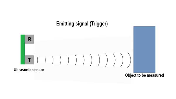
In the image above, you can see that the sensor generates an ultrasonic pulse (an invisible high-frequency signal). This pulse propagates through the air in a straight line until it encounters an obstacle. The emitted waves travel at a constant speed, roughly equal to the speed of sound in air (approximately 343 meters per second at room temperature).
Echo Reception
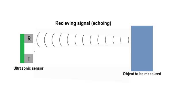
Once the sound wave strikes an object, it reflects and travels back to the sensor, as illustrated in the image above. The sensor’s receiver detects this returning signal and records the time delay between transmission and reception.
Distance Calculation
The distance between the sensor and the object is determined using the following formula:

The division by two accounts for the round-trip travel of the sound wave outward to the object and back to the sensor.
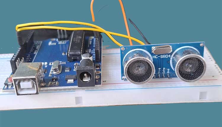
The most commonly used ultrasonic sensor with Arduino is the HC-SR04, which is known for its affordability, reliability, and ease of use. It has four pins:
- VCC – Power supply (5V)
- Trig – Trigger input to send ultrasonic pulses
- Echo – Receives the reflected (returning ) signal
- GND – Ground connection
Key Specifications of the HC-SR04
- Working Voltage: 5V DC
- Working Current: 15mA
- Working Frequency: 40kHz
- Measuring Range: 2cm to 400cm
- Measuring Angle: 15 degrees
- Resolution: Up to 3mm
Ultarsonic & Arduino Hardware Setup
Components Needed
- Arduino board (Uno, Nano, Mega, etc.)
- HC-SR04 ultrasonic sensor
- Breadboard
- Jumper wires
- Optional: LED, buzzer, or display for output
Connection Diagram
Connecting the HC-SR04 to your Arduino is straightforward as illustrated in the diagram below:
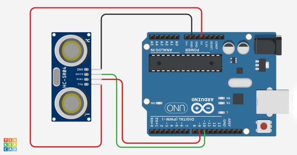
- Connect VCC on the sensor to 5V on the Arduino
- Connect GND on the sensor to GND on the Arduino
- Connect Trig on the sensor to a digital pin (Here, I used pin 9)
- Connect Echo on the sensor to another digital pin (Here, I used pin 10)
Programming the Arduino
Basic Distance Measurement Code
// Define pins
const int trigPin = 9;
const int echoPin = 10;

// Define variables
long duration;
int distance;

void setup() {
  // Initialize Serial communication
  Serial.begin(9600);

  // Set pin modes
  pinMode(trigPin, OUTPUT);
  pinMode(echoPin, INPUT);
}

void loop() {
  // Clear the trigPin
  digitalWrite(trigPin, LOW);
  delayMicroseconds(2);

  // Set the trigPin HIGH for 10 microseconds
  digitalWrite(trigPin, HIGH);
  delayMicroseconds(10);
  digitalWrite(trigPin, LOW);

  // Read the echoPin, calculate distance
  duration = pulseIn(echoPin, HIGH);
  distance = duration * 0.034 / 2; // Speed of sound wave divided by 2 (go and back)

  // Display the distance on the Serial Monitor
  Serial.print("Distance: ");
  Serial.print(distance);
  Serial.println(" cm");

  delay(500); // Wait before next measurement
}
Understanding the Code
The code follows these steps:
- Setup: Configure the trigger pin as output and the echo pin as input
- Trigger the sensor: Send a 10-microsecond pulse to the trigger pin
- Measure echo time: Use
pulseIn()to measure how long it takes for the echo to return - Calculate distance: Convert the time to distance using the speed of sound
- Display results: Show the distance in the Serial Monitor
The Math Behind Distance Calculation
The formula distance = duration * 0.034 / 2 is based on:
- Sound travels at approximately 343 meters/second (or 0.034 cm/microsecond) in air at room temperature
- We divide by 2 because the sound wave travels to the object and back
Practical Projects
1. Simple Distance Alarm
Create a system that triggers an alarm when an object comes within a certain distance:
const int trigPin = 9;
const int echoPin = 10;
const int buzzerPin = 7;
const int thresholdDistance = 20; // in centimeters

void setup() {
  Serial.begin(9600);
  pinMode(trigPin, OUTPUT);
  pinMode(echoPin, INPUT);
  pinMode(buzzerPin, OUTPUT);
}

void loop() {
  long duration;
  int distance;

  digitalWrite(trigPin, LOW);
  delayMicroseconds(2);
  digitalWrite(trigPin, HIGH);
  delayMicroseconds(10);
  digitalWrite(trigPin, LOW);

  duration = pulseIn(echoPin, HIGH);
  distance = duration * 0.034 / 2;

  Serial.print("Distance: ");
  Serial.print(distance);
  Serial.println(" cm");

  if (distance < thresholdDistance) {
    digitalWrite(buzzerPin, HIGH);
  } else {
    digitalWrite(buzzerPin, LOW);
  }

  delay(300);
}
2. Parking Assistant
Help guide a car into a garage by using LEDs to indicate distance:
const int trigPin = 9;
const int echoPin = 10;
const int greenLED = 7;
const int yellowLED = 6;
const int redLED = 5;

void setup() {
  Serial.begin(9600);
  pinMode(trigPin, OUTPUT);
  pinMode(echoPin, INPUT);
  pinMode(greenLED, OUTPUT);
  pinMode(yellowLED, OUTPUT);
  pinMode(redLED, OUTPUT);
}

void loop() {
  long duration;
  int distance;

  digitalWrite(trigPin, LOW);
  delayMicroseconds(2);
  digitalWrite(trigPin, HIGH);
  delayMicroseconds(10);
  digitalWrite(trigPin, LOW);

  duration = pulseIn(echoPin, HIGH);
  distance = duration * 0.034 / 2;

  Serial.print("Distance: ");
  Serial.print(distance);
  Serial.println(" cm");

  // Turn all LEDs off
  digitalWrite(greenLED, LOW);
  digitalWrite(yellowLED, LOW);
  digitalWrite(redLED, LOW);

  // Turn on appropriate LED based on distance
  if (distance > 100) {
    digitalWrite(greenLED, HIGH); // Far away
  } else if (distance > 50) {
    digitalWrite(yellowLED, HIGH); // Getting closer
  } else {
    digitalWrite(redLED, HIGH); // Very close - stop!
  }

  delay(300);
}
3. Water Level Monitor
const int trigPin = 9;
const int echoPin = 10;
const int containerHeight = 30; // Height of your container in cm

void setup() {
  Serial.begin(9600);
  pinMode(trigPin, OUTPUT);
  pinMode(echoPin, INPUT);
}

void loop() {
  long duration;
  int distance;
  int waterLevel;
  int percentFull;

  digitalWrite(trigPin, LOW);
  delayMicroseconds(2);
  digitalWrite(trigPin, HIGH);
  delayMicroseconds(10);
  digitalWrite(trigPin, LOW);

  duration = pulseIn(echoPin, HIGH);
  distance = duration * 0.034 / 2;

  // Calculate water level (assuming sensor is mounted above container)
  waterLevel = containerHeight - distance;
  if (waterLevel < 0) waterLevel = 0; // Handle out-of-range readings

  // Calculate percentage full
  percentFull = (waterLevel * 100) / containerHeight;

  Serial.print("Water level: ");
  Serial.print(waterLevel);
  Serial.print(" cm (");
  Serial.print(percentFull);
  Serial.println("%)");

  delay(1000);
}
Troubleshooting Common Issues
Inaccurate Readings
If you’re getting inconsistent or inaccurate readings:
- Environmental factors: Temperature affects the speed of sound. For precise measurements, you can add temperature compensation:
// With a temperature sensor (e.g., TMP36)
float temperatureC = (analogRead(A0) * 5.0 / 1024.0 - 0.5) * 100;
float speedOfSound = 331.3 + (0.606 * temperatureC); // in m/s
distance = duration * speedOfSound / 20000; // in cm
- Surface properties: Soft, irregular, or angled surfaces might not reflect sound waves effectively.
- Interference: Multiple ultrasonic sensors can interfere with each other. Ensure they’re separated or trigger them sequentially.
No Readings or Out-of-Range Values
- Check wiring: Ensure all connections are secure.
- Power supply: Confirm the sensor is receiving adequate 5V power.
- Distance limits: Remember the HC-SR04 has a range of 2cm to 400cm.
Noisy Signal
- Add filtering: Implement a simple moving average to smooth readings:
const int numReadings = 10;
int readings[numReadings];
int readIndex = 0;
int total = 0;
int average = 0;

void setup() {
  // Initialize all readings to 0
  for (int i = 0; i < numReadings; i++) {
    readings[i] = 0;
  }
}

void loop() {
  // Get distance measurement as before

  // Subtract the last reading
  total = total - readings[readIndex];
  // Add the new reading
  readings[readIndex] = distance;
  total = total + readings[readIndex];
  // Advance to the next position in the array
  readIndex = (readIndex + 1) % numReadings;

  // Calculate the average
  average = total / numReadings;

  Serial.print("Smoothed distance: ");
  Serial.print(average);
  Serial.println(" cm");
}
Advanced Techniques
Using Multiple Sensors
For projects requiring broader coverage or object tracking, you can use multiple ultrasonic sensors:
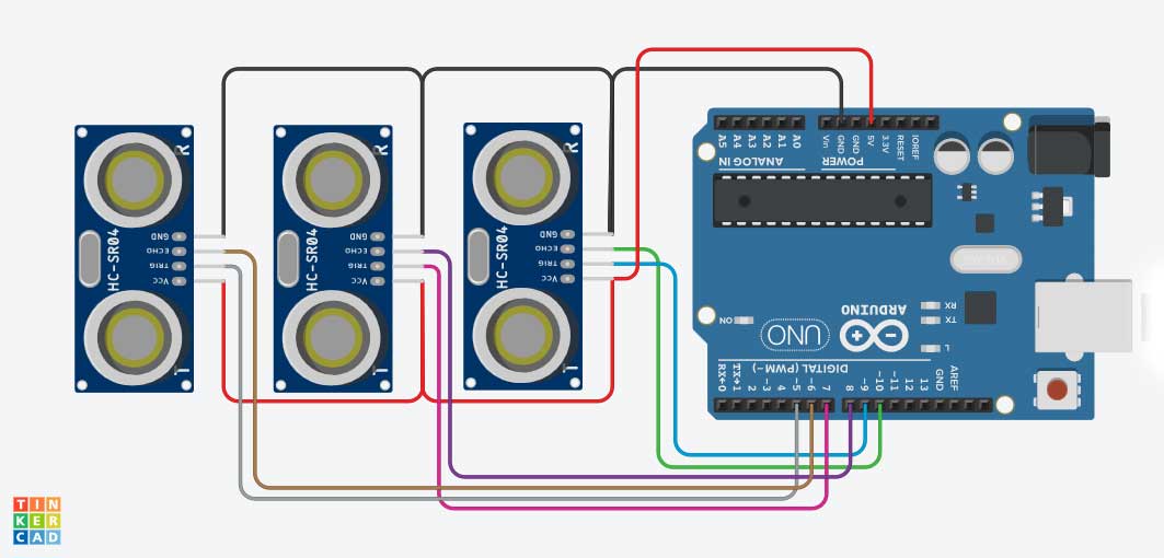
Core for Multiple Ultrasonic Sensors with Arduino
const int trigPins[] = {9, 7, 5};
const int echoPins[] = {10, 8, 6};
const int numSensors = 3;

void setup() {
  Serial.begin(9600);
  for (int i = 0; i < numSensors; i++) {
    pinMode(trigPins[i], OUTPUT);
    pinMode(echoPins[i], INPUT);
  }
}

void loop() {
  for (int i = 0; i < numSensors; i++) {
    int distance = measureDistance(trigPins[i], echoPins[i]);

    Serial.print("Sensor ");
    Serial.print(i);
    Serial.print(": ");
    Serial.print(distance);
    Serial.println(" cm");
  }
  Serial.println();
  delay(500);
}

int measureDistance(int trigPin, int echoPin) {
  digitalWrite(trigPin, LOW);
  delayMicroseconds(2);
  digitalWrite(trigPin, HIGH);
  delayMicroseconds(10);
  digitalWrite(trigPin, LOW);

  long duration = pulseIn(echoPin, HIGH);
  return duration * 0.034 / 2;
}
Non-Blocking Measurements
For more responsive projects, use non-blocking techniques:
unsigned long previousMillis = 0;
const long interval = 100; // Measurement interval in milliseconds
int distance = 0;

void setup() {
  Serial.begin(9600);
  pinMode(trigPin, OUTPUT);
  pinMode(echoPin, INPUT);
}

void loop() {
  unsigned long currentMillis = millis();

  // Other code can run here without being delayed

  if (currentMillis - previousMillis >= interval) {
    previousMillis = currentMillis;

    // Measure distance
    digitalWrite(trigPin, LOW);
    delayMicroseconds(2);
    digitalWrite(trigPin, HIGH);
    delayMicroseconds(10);
    digitalWrite(trigPin, LOW);

    long duration = pulseIn(echoPin, HIGH);
    distance = duration * 0.034 / 2;

    Serial.print("Distance: ");
    Serial.print(distance);
    Serial.println(" cm");
  }

  // More code can run here
}
Integrating with Other Sensors and Outputs
With an LCD Display
#include <LiquidCrystal.h>

// Initialize the LCD
LiquidCrystal lcd(12, 11, 5, 4, 3, 2);

void setup() {
  pinMode(trigPin, OUTPUT);
  pinMode(echoPin, INPUT);

  lcd.begin(16, 2); // Set up the LCD's number of columns and rows
  lcd.print("Distance Sensor");
}

void loop() {
  // Measure distance as before

  // Display on LCD
  lcd.setCursor(0, 1);
  lcd.print("Distance: ");
  lcd.print(distance);
  lcd.print(" cm   ");

  delay(300);
}
Ultrasonic Sensor with a Servo Motor for Object Tracking
An ultrasonic sensor paired with a servo motor can be used for object tracking by continuously scanning an area and detecting obstacles. The servo motor adjusts its angle based on the object’s detected position, enabling real-time tracking. This setup is commonly used in robotics, security systems, and automation projects. Check the connection diagram and sample code below:
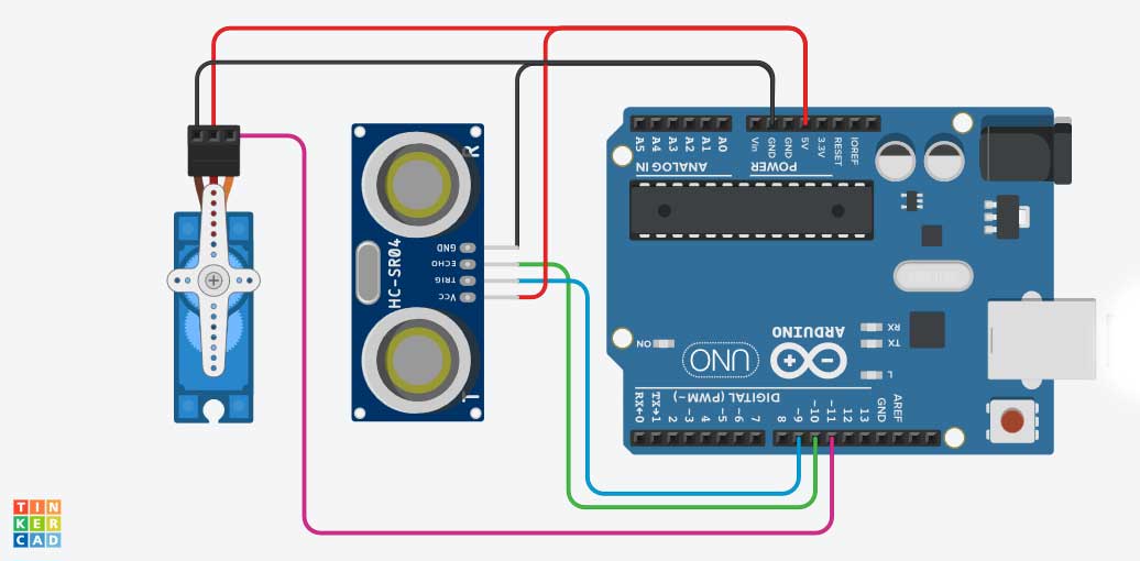
Code for Ultrasonic Sensor with a Servo Motor
#include <Servo.h>

Servo myServo;
const int servoPin = 11;

void setup() {
  Serial.begin(9600);
  pinMode(trigPin, OUTPUT);
  pinMode(echoPin, INPUT);

  myServo.attach(servoPin);
  myServo.write(90); // Start at middle position
}

void loop() {
  // Measure distance as before

  // Map distance to servo angle (closer objects = higher angle)
  int angle = map(distance, 5, 100, 180, 0);
  angle = constrain(angle, 0, 180);

  myServo.write(angle);

  Serial.print("Distance: ");
  Serial.print(distance);
  Serial.print(" cm, Angle: ");
  Serial.println(angle);

  delay(100);
}
Conclusion
Ultrasonic sensors are versatile components that can enhance your Arduino projects with distance-sensing capabilities. From simple distance measurement to complex object detection systems, these sensors offer a cost-effective way to interact with the physical world.
By understanding how ultrasonic sensors work and mastering the techniques covered in this guide, you can create more interactive and responsive Arduino projects. Whether you’re building a robot, a security system, or an automated home solution, ultrasonic sensors provide the “eyes” your projects need to perceive the environment.
Additional Resources
- Arduino Official Documentation
- HC-SR04 Datasheet
- Introduction to Electronics
- Beginner’s Guide to Arduino
Remember that practice is key to mastering any technology. Start with simple projects and gradually work your way up to more complex implementations. If you need a specific circuit diagram for any of the sample projects discussed above, please mention it in the comments, and I’ll be happy to help!
Happy tinkering!