



2-Channel 5V Relay Module with High/Low Trigger
₵20.00
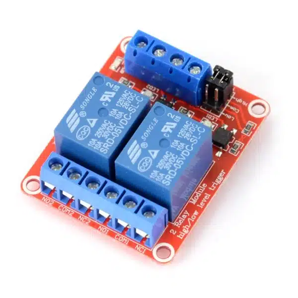
The 2-Channel 5V Relay Module with High/Low Trigger lets Arduino, ESP32 and other compatible microcontrollers control two electrical circuits independently. It features optocoupler inputs, selectable HIGH/LOW triggering for each channel, 10A relay contacts and LED indicators for automation and robotics projects.
30 in stock
The 2-Channel 5V Relay Module is a compact electronic switching board designed to control two separate electrical circuits using Arduino, ESP32 and other compatible microcontrollers.
Unlike conventional fixed-trigger relay modules, this version supports independent HIGH or LOW trigger selection for each channel through onboard jumper switches.
It features two 5V electromagnetic relays, optocoupler input circuits, relay status indicators and screw terminals for convenient wiring. The module is suitable for home automation, robotics, lighting control, electronic switching and STEM projects.
Key Features
- Two Independent Relay Channels: Control two external circuits separately.
- 5V DC Operation: Uses a regulated 5V power supply.
- Selectable HIGH/LOW Trigger: Configure each relay to respond to a HIGH or LOW control signal.
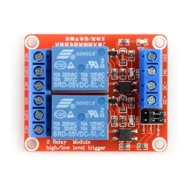
- Individual Trigger Jumpers: S1 and S2 provide independent trigger selection.
- Optocoupler Inputs: Reduce electrical interference between the control signals and relay driver circuits.
- 10A Relay Contacts: Relay components support switching loads within their specified AC and DC ratings.
- NO, NC and COM Terminals: Flexible switching connections for each channel.
- LED Status Indicators: Display module power and relay activation.
- Screw Terminal Connections: Convenient connection of external circuits.
- PCB Mounting Holes: Allow installation inside suitable project enclosures.
Technical Specifications
| Specification | Details |
|---|---|
| Product Type | 2-Channel Relay Module |
| Operating Voltage | 5V DC |
| Number of Channels | 2 |
| Relay Configuration | SPDT |
| Trigger Type | HIGH / LOW Selectable |
| Trigger Selection | S1 and S2 Jumpers |
| Input Interface | IN1, IN2 |
| Power Supply Terminals | DC+, DC- |
| Output Contacts | NO, COM, NC per relay |
| Relay Contact Rating | 10A at 250V AC |
| DC Contact Rating | 10A at 30V DC |
| Input Circuit | Optocoupler-Based |
| Status Indicators | Power and Relay LEDs |
| Connection Type | Screw Terminals |
| PCB Colour | Red |
| Number of Relays | 2 |
Applications
1. Arduino Automation Projects
Control two separate electrical devices using a microcontroller.
Pair this module with the Arduino Uno R3 Development Board to build programmable switching systems.
2. Smart Home Projects
Develop automatic lighting, fan control, alarms and other switching applications.
3. Water Pump Automation
Use the relay module with suitable water-level sensors and correctly rated motor-switching equipment to develop automatic water control systems.
4. Robotics and Embedded Systems
Control external actuators, indicators and suitable low-voltage electrical devices.
5. Timer and Sensor-Based Control
Create circuits that switch external loads according to programmed schedules, sensor readings or manual commands.
6. Electronics Education
Demonstrate electromagnetic relay operation, digital switching, optocoupler circuits and HIGH/LOW trigger logic in practical STEM lessons.
How the 2-Channel 5V Relay Module Works
Each channel contains an electromagnetic relay that acts as an electrically operated switch.
When a control signal is applied to IN1 or IN2, the corresponding relay responds according to its selected trigger mode.
When a relay activates, its Common (COM) contact switches from Normally Closed (NC) to Normally Open (NO).
The two channels operate independently.
HIGH and LOW Trigger Selection
The module includes two jumper selectors.
| Selector | Function |
|---|---|
| S1 | Selects HIGH or LOW triggering for Relay 1 |
| S2 | Selects HIGH or LOW triggering for Relay 2 |
HIGH-Level Trigger
Connect the corresponding selector between HIGH and COM.
The relay activates when its input receives a suitable HIGH signal.
LOW-Level Trigger
Connect the selector between LOW and COM.
The relay activates when its input is driven LOW.
For example, Relay 1 can use HIGH-level triggering while Relay 2 uses LOW-level triggering.
Control and Power Connections
| Terminal | Function |
|---|---|
| DC+ | Positive 5V supply |
| DC- | Ground / Negative supply |
| IN1 | Relay 1 control input |
| IN2 | Relay 2 control input |
Connecting to Arduino Uno
For a basic two-relay control project:
| Relay Module | Arduino Uno |
|---|---|
| DC+ | Regulated 5V supply |
| DC- | GND |
| IN1 | Digital Pin D7 |
| IN2 | Digital Pin D8 |
Configure S1 and S2 for the desired triggering behaviour.
When using a separate relay power supply, ensure that the control signals have the appropriate common reference.
For convenient microcontroller wiring, DIYGH stocks Male-to-Female Jumper Wires.
Understanding NO, NC and COM Contacts
Each relay provides three switching terminals.
COM (Common): The shared terminal used by the moving relay contact.
NO (Normally Open): Disconnected from COM when the relay is inactive. Connected to COM when activated.
NC (Normally Closed): Connected to COM when the relay is inactive. Disconnected when activated.
These contacts allow users to choose whether an external circuit should normally remain connected or disconnected.
Choosing the Right Relay Module
For projects requiring only one switching circuit, DIYGH stocks the 1-Channel 5V Relay Module.
For projects requiring four independent switching circuits, consider the 4-Channel 5V Relay Module.
This 2-channel module provides a compact option for projects needing two outputs, with the additional convenience of individually selectable trigger logic.
Important Usage Information
- Supply the module with regulated 5V DC.
- Select the appropriate HIGH/LOW trigger mode before operating each channel.
- Disconnect power before changing relay wiring.
- Verify control-signal compatibility before connecting 3.3V microcontrollers.
- Do not power relay coils directly from microcontroller GPIO pins.
- Ensure the 5V supply can support both relay coils during simultaneous operation.
- Optocoupler inputs help reduce interference but do not automatically guarantee complete electrical isolation.
- Use suitable contact protection when switching motors, solenoids and other inductive loads.
- The relay contact ratings do not establish the safe mains-switching rating of the entire PCB assembly.
- Mains-powered installations require appropriate enclosures, protection devices and qualified electrical installation.
Package Includes
- 1 x 2-Channel 5V Relay Module with HIGH/LOW Trigger Selection
Microcontroller, connecting wires, power supply and enclosure are not included.
Related products
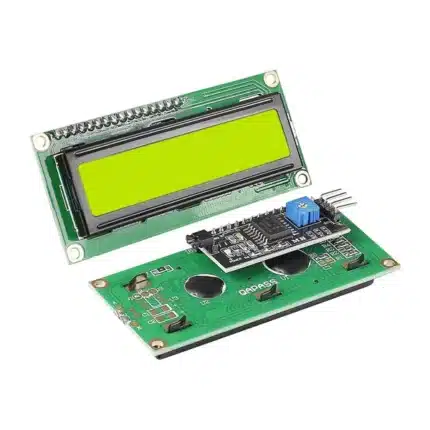
16×2 LCD Display with I2C Interface – Yellow Backlight
A clear, beginner-friendly 16×2 character display with the I2C backpack already soldered. The yellow-green backlight provides excellent readability while the I2C interface reduces wiring to only four connections.
Display: 16 characters × 2 lines
Backlight: Yellow-Green
Interface: I2C (VCC, GND, SDA, SCL)
Voltage: 5V DC
Contrast: Adjustable
Installation: Ready to use – no backpack soldering required
Best For: Arduino, ESP32, Raspberry Pi, IoT and educational projects
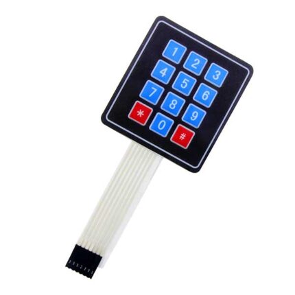
3×4 Matrix Membrane Keypad Module | 12 Button Numeric Pad
A simple and reliable input device for Arduino and DIY electronics projects. This flexible 12-key keypad provides only the essential keys (0–9, *, #)—no letters—making it ideal for numeric-only applications. It comes with a peel-and-stick adhesive backing for quick mounting on enclosures, panels, or doors.
-
Keys: 12 (Telephone-style layout)
-
Interface: 7 pins (2.54 mm standard pitch)
-
Mounting: Self-adhesive sticker backing
- Best for: Electronic door locks, vending machines, access control systems, phone dialers, and keypad-based Arduino projects.

433MHz RF Transmitter & Receiver Kit | Wireless Module for Arduino
Cut the cord. Go wireless. This kit includes one Transmitter and one Receiver. It is the simplest and most affordable way to send data wirelessly between two Arduinos up to 100 meters (with antenna).
-
Frequency: 433MHz
-
Includes: 1x Transmitter (Square), 1x Receiver (Rectangle)
-
Modulation: ASK (Amplitude Shift Keying)
-
Best For: Remote control cars, weather stations, and wireless switches.
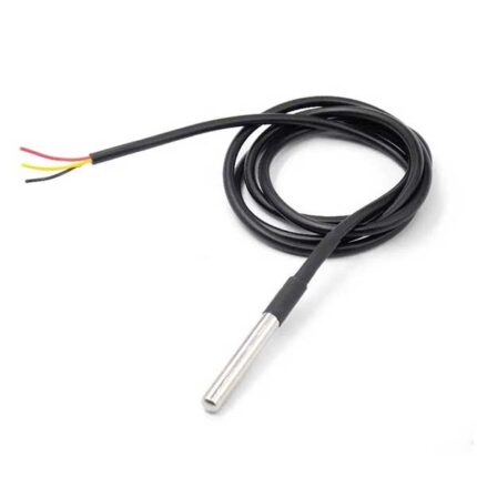
DS18B20 Waterproof Temperature Sensor Probe | Stainless Steel Digital Thermometer
Measure liquid temperature with digital precision. This is the waterproof version of the famous DS18B20 sensor. Encased in a stainless steel tube, it is perfect for measuring water, soil, or air temperature in harsh environments.
-
Range: -55°C to +125°C
-
Interface: 1-Wire Digital (Requires only 1 pin)
-
Cable Length: 1 Meter
-
Best For: Aquariums, boilers, soil temperature, and cold chain monitoring.
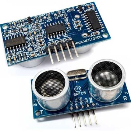
HC-SR04 Ultrasonic Sensor Module | Distance Measurement for Arduino
Give your robot eyes. The HC-SR04 uses sonar (sound waves) to measure distance, just like a bat. It is the standard sensor for obstacle avoidance robots and water level monitoring systems.
-
Range: 2cm to 400cm (4 Meters)
-
Accuracy: 3mm
-
Pins: VCC, Trig, Echo, GND
-
Best For: Obstacle avoiding cars, reverse parking sensors, and tank level detection.

HC-SR501 PIR Motion Sensor Module | Infrared Detector for Arduino
Build your own burglar alarm or automatic light. The HC-SR501 detects human and animal movement by sensing body heat. It is the standard motion sensor for Arduino security projects.
-
Range: Adjustable (3 to 7 meters)
-
Output: 3.3V Logic (High when motion detected)
-
Features: Adjustable Time Delay & Sensitivity
-
Ideal For: Automated lighting, security systems, and robotics.

High Sensitivity Vibration Sensor Module (SW-1801P) | Shock & Shake Switch
Detect even the slightest tap. Unlike standard vibration sensors that require a hard shake, the SW-1801P High Sensitivity module can detect light knocks, impacts, and vibrations. Perfect for anti-theft alarms and "Smart Wake-Up" devices.
-
Sensor Type: SW-1801P (High Sensitivity Spring).
-
Output: Digital (High/Low).
-
Adjustable: Blue Potentiometer to set sensitivity trigger.
-
Best For: Anti-Theft Alarms, Earthquake Detection, and Smart Toys.

NEO-6M GPS Module V2 with Ceramic Antenna | Flight Controller & Tracker
Add Satellite Navigation to your project. This high-precision GPS module allows your Arduino, ESP32, or Drone to know its exact location, speed, and time. It comes with a detachable ceramic antenna and a built-in backup battery for fast "Hot Starts."
-
Chipset: U-Blox NEO-6M.
-
Antenna: High-gain Active Ceramic Antenna (Included).
-
Data Retention: EEPROM + Battery (Saves configuration).
-
Best For: Drone Flight Controllers, Vehicle Trackers, and Speedometers.
Reviews
There are no reviews yet.