


4-Channel Relay Module with High/Low Trigger (5V)
₵40.00
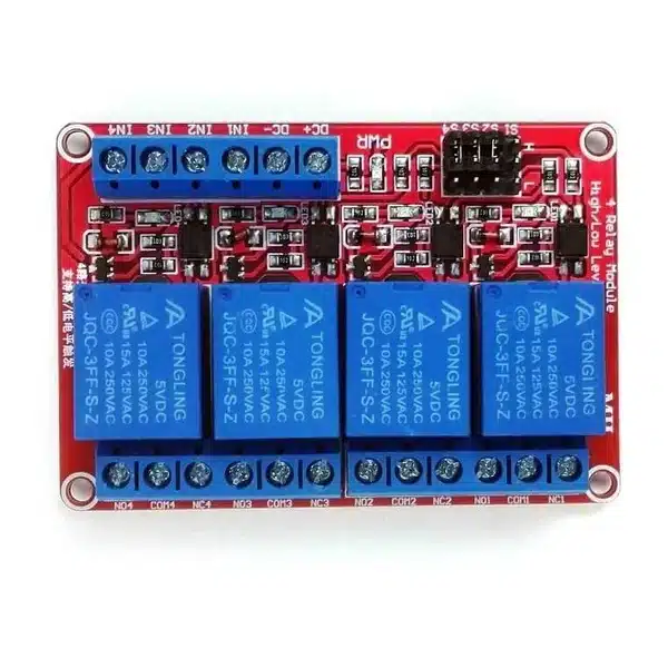
The 4-Channel Relay Module with High/Low Trigger (5V) allows Arduino, ESP32 and other microcontrollers to control four electrical circuits independently. It features optocoupler inputs, individually selectable HIGH/LOW triggering, 10A relay contacts and LED status indicators for automation, robotics and smart control projects.
30 in stock
The 4-Channel Relay Module with High/Low Trigger is a versatile electronic switching board designed to control four separate electrical circuits using Arduino, ESP32 and other compatible microcontrollers.
Unlike conventional relay boards that operate with only LOW-level triggering, this module allows each relay channel to be configured independently for HIGH or LOW triggering using onboard jumper selectors.
It features four electromagnetic relays, optocoupler input circuits, screw terminal connections and LED status indicators, making it suitable for automation, robotics, smart home systems and electrical control projects.
Key Features
- 4 Independent Relay Channels: Control up to four separate electrical circuits.
- Selectable HIGH/LOW Triggering: Configure each relay individually using jumper selectors S1-S4.
- 5V DC Operation: Designed for the selected 5V relay version.
- 10A Relay Contacts: Relay components rated for specified AC and DC switching loads.
- Optocoupler Inputs: Help reduce electrical interference between the control signals and relay driver circuits.
- NO, NC and COM Contacts: Flexible switching arrangements for each relay.
- LED Indicators: Individual indicators display relay activation status.
- Screw Terminal Connections: Convenient connections for power, control signals and external loads.
- Four Mounting Holes: Allow secure installation inside project enclosures.
Technical Specifications
| Specification | Details |
|---|---|
| Product Type | 4-Channel Relay Module |
| Selected Version | 5V DC |
| Number of Channels | 4 |
| Relay Type | Electromagnetic SPDT |
| Trigger Mode | HIGH / LOW Selectable |
| Trigger Selection | S1, S2, S3, S4 Jumpers |
| Relay Contact Rating | 10A at 250V AC |
| DC Contact Rating | 10A at 30V DC |
| Control Inputs | IN1, IN2, IN3, IN4 |
| Power Connections | DC+, DC- |
| Relay Outputs | NO, COM, NC for Each Channel |
| Optocoupler Inputs | Yes |
| Status Indicators | Power and Relay LEDs |
| Connector Type | Screw Terminals |
| PCB Colour | Red |
| Mounting | Four PCB Mounting Holes |
Applications
1. Arduino Home Automation
Use the module to control four independent electrical circuits from a single Arduino development board.
For example, the Arduino Uno R3 Development Board can provide digital control signals for operating different relay channels.
2. Smart Home and IoT Projects
Create programmable switching systems for lighting, ventilation, alarms and compatible electrical equipment.
3. Automatic Water Pump Control
Use the relay board as part of a water level monitoring and automatic pump control system, with properly rated external switching equipment where required.
4. Robotics and Automation
Control suitable solenoids, actuators, indicator circuits and other electrical loads from a microcontroller.
5. Timer-Based Switching
Build automatic switching systems that activate or deactivate different devices according to programmed time schedules.
6. STEM and Electrical Education
Demonstrate electromagnetic relays, digital logic, optocoupler circuits, HIGH/LOW trigger selection and multi-channel electrical control.
How the 4-Channel Relay Module Works
Each relay functions as an electrically operated switch.
A microcontroller sends a digital signal to one of the four control inputs. Depending on the corresponding jumper setting, the relay activates when the input becomes HIGH or LOW.
When activated, the relay changes the connection between its Common (COM), Normally Open (NO) and Normally Closed (NC) contacts.
Each channel operates independently, allowing four different circuits to be controlled from one board.
HIGH and LOW Trigger Selection
The module contains four jumper selectors labelled S1, S2, S3 and S4.
Each selector corresponds to one relay channel.
| Jumper | Relay Channel |
|---|---|
| S1 | Relay 1 |
| S2 | Relay 2 |
| S3 | Relay 3 |
| S4 | Relay 4 |
The jumper header provides three positions: LOW, COM and HIGH.
LOW-Level Trigger
Connect the jumper between LOW and COM. The corresponding relay activates when its control input receives a LOW signal.
HIGH-Level Trigger
Connect the jumper between HIGH and COM. The corresponding relay activates when its control input receives a HIGH signal.
All four relays can use the same trigger mode, or each can be configured differently.
Power Supply and Control Connections
| Terminal | Function |
|---|---|
| DC+ | Positive module supply |
| DC- | Ground / Negative supply |
| IN1 | Relay 1 Control Input |
| IN2 | Relay 2 Control Input |
| IN3 | Relay 3 Control Input |
| IN4 | Relay 4 Control Input |
A separate power supply may be necessary if the microcontroller cannot supply sufficient current for all four relay coils.
Connecting to Arduino Uno
A typical control connection is:
| Relay Module | Arduino Uno |
|---|---|
| DC+ | Regulated 5V Supply |
| DC- | GND |
| IN1 | D2 |
| IN2 | D3 |
| IN3 | D4 |
| IN4 | D5 |
Configure S1-S4 for the required trigger logic.
Connect the Arduino ground to the module’s control ground and ensure the selected input signal levels are compatible.
For prototyping and convenient connections, DIYGH stocks Male-to-Female Jumper Wires.
Understanding the Relay Output Terminals
Each relay provides three electrical contacts.
- COM (Common): The shared switching terminal.
- NO (Normally Open): Connects to COM when the relay activates.
- NC (Normally Closed): Connects to COM when the relay is inactive.
These connections allow the module to control circuits that should turn ON or OFF when a relay is activated.
The external load circuit is electrically separate from the low-voltage relay control signal.
Selectable Trigger vs Fixed LOW-Level Trigger
The main advantage of this board is its flexible trigger configuration.
The HIGH/LOW selection allows developers to choose the control logic that best suits their programmed application.
For projects requiring only LOW-level triggering, DIYGH also stocks the 4-Channel 5V Relay Module with Fixed LOW-Level Trigger.
For simpler projects requiring just one switching circuit, consider the 1-Channel 5V Relay Module.
Important Usage Information
- Use the supply voltage specified for the actual relay coil version.
- Disconnect power before changing trigger jumpers or terminal wiring.
- Check that the input signal voltage is compatible with the relay module.
- Verify HIGH/LOW triggering before connecting important equipment.
- Optocoupler inputs do not guarantee complete galvanic isolation if the control and relay circuits share a power supply.
- The relay contact ratings do not automatically establish the safe switching limits of the complete module.
- Use suitable protection when switching motors, pumps and other inductive loads.
- Ensure the PCB is securely mounted and protected from accidental contact.
- For mains-powered applications, use a qualified electrician, suitable enclosures, protective devices and properly rated wiring.
Package Includes
- 1 x 4-Channel Relay Module with HIGH/LOW Trigger Selection (5V Version)
Microcontroller, connection wires, external power supply and enclosure are not included.
Related products
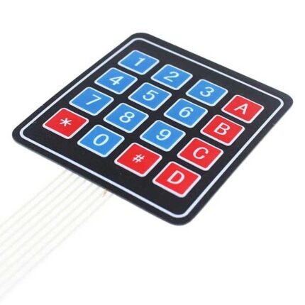
4×4 Matrix Membrane Keypad | 16 Button Keypad Module
The standard keypad for security projects. This ultra-thin 16-button keypad allows users to enter passwords, navigate menus, or control robots. It features a peel-and-stick adhesive backing, making it easy to mount on any plastic project box or door.
-
Keys: 16 (0-9, A-D, *, #)
-
Mounting: Self-Adhesive Backing (Peel & Stick)
-
Interface: 8 Pins (Standard 2.54mm header)
-
Best For: Electronic Door Locks, Calculators, and Attendance Systems.
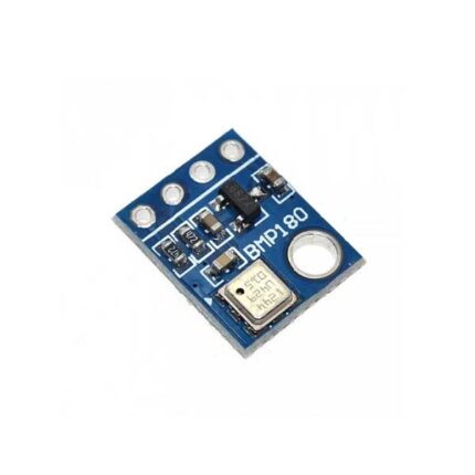
BMP180 Digital Barometric Pressure & Altitude Sensor Module
Predict the weather or measure your altitude. The BMP180 is a high-precision sensor that measures air pressure and temperature. Because pressure changes with height, it also works as an incredibly accurate altimeter (±1 meter accuracy).
-
Measures: Pressure (Pa) & Temperature (C)
-
Interface: I2C (SDA/SCL)
-
Voltage: 3.3V to 5V Compatible
-
Best For: Weather stations, Drones, and GPS altitude correction.

DS3231 RTC Real-Time Clock Module
The DS3231 is a highly accurate I2C real-time clock (RTC) with an integrated temperature-compensated crystal oscillator (TCXO).
-
Chip: Maxim DS3231 (High Precision)
-
Memory: Built-in AT24C32 32K I2C EEPROM
-
Voltage: 3.3V – 5.5V DC
-
Interface: I2C (SCL, SDA)
-
Battery Backup: Holds time when power is off (Coin cell slot included)
-
Accuracy: Much higher than the standard DS1307

High Sensitivity Vibration Sensor Module (SW-1801P) | Shock & Shake Switch
Detect even the slightest tap. Unlike standard vibration sensors that require a hard shake, the SW-1801P High Sensitivity module can detect light knocks, impacts, and vibrations. Perfect for anti-theft alarms and "Smart Wake-Up" devices.
-
Sensor Type: SW-1801P (High Sensitivity Spring).
-
Output: Digital (High/Low).
-
Adjustable: Blue Potentiometer to set sensitivity trigger.
-
Best For: Anti-Theft Alarms, Earthquake Detection, and Smart Toys.
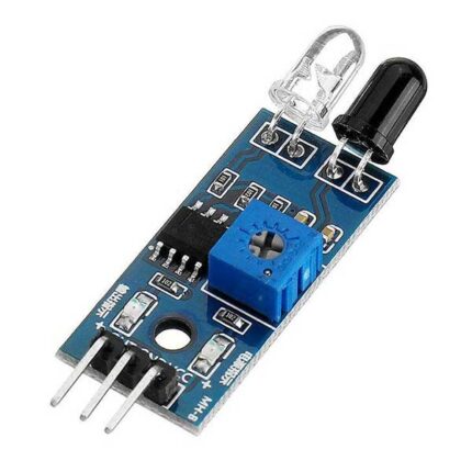
IR Infrared Obstacle Avoidance Sensor Module | FC-51 for Arduino
Teach your robot to see. This sensor emits infrared light and detects reflections to see if an object is in front of it. It is the essential component for building "Obstacle Avoiding Robots" and simple security alarms.
-
Detection Range: 2cm - 30cm (Adjustable).
-
Output: Digital Signal (LOW when obstacle detected).
-
Compatibility: Works directly with Arduino, ESP32, and Raspberry Pi.
-
Best For: Robot Cars, Smart Trash Cans, and Proximity Alarms.

LDR Photosensitive Sensor Module (4-Pin) | Light Detector
Make your project react to light. This sensor detects the brightness of the environment. Unlike the 3-pin version, this 4-Pin Module gives you both a Digital Output (to trigger a switch) and an Analog Output (to measure exact brightness). Perfect for automatic streetlights and solar trackers.
- Sensor Type: Light Dependent Resistor (Photoresistor).
-
Outputs: Digital (D0) & Analog (A0).
-
Sensitivity: Adjustable via Blue Potentiometer.
- Best For: Automatic Lights, Sun Trackers, and Laser Tripwires.

MQ-3 Alcohol Sensor Module | Breathalyzer & Ethanol Detector
Build your own Breathalyzer. The MQ-3 is specifically designed to detect alcohol (Ethanol) vapors. It has high sensitivity and fast response time, making it the perfect sensor for "Smart Car" safety systems that prevent drunk driving.
-
Detects: Alcohol, Ethanol, Benzine.
-
Sensitivity: Adjustable via Blue Potentiometer.
-
Warm-up: Heater requires ~20 seconds.
-
Best For: Breathalyzers, Drunk Driving Alarms, and Industrial Monitoring.

Reviews
There are no reviews yet.