

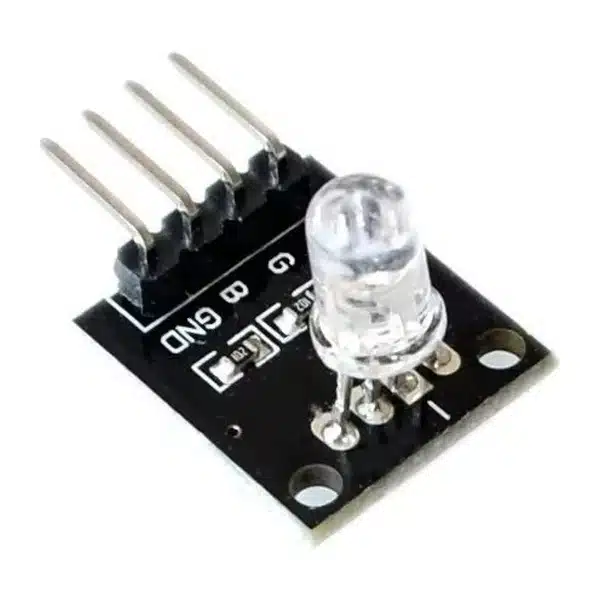
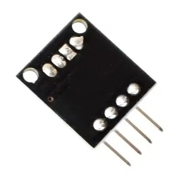


RGB LED Module 5mm 4-Pin (Full Colour)
₵7.00
The RGB LED Module 5mm 4-Pin combines red, green and blue light to produce different colours using Arduino, ESP32 and other microcontrollers. Featuring a common-cathode design and individual RGB control pins, it is ideal for colourful lighting effects, status indicators and STEM electronics projects.
50 in stock
The RGB LED Module 5mm is a compact, full-colour LED module designed for creating colourful lighting effects in Arduino, ESP32, robotics and electronics projects.
It combines three LED colours – Red, Green and Blue – inside a single transparent 5mm LED package. By controlling the brightness of each colour independently, users can create a wide range of colours, including yellow, cyan, magenta and white.
The module features a black PCB, four connection pins and two mounting holes, making it convenient for electronics prototyping, educational demonstrations and custom lighting applications.
Key Features
- Full-Colour RGB LED: Combines red, green and blue light to produce multiple colours.
- 5mm Transparent LED: Compact through-hole RGB LED mounted on a small PCB.
- 4-Pin Interface: Separate Red, Green and Blue connections with a common ground.
- PWM Brightness Control: Adjust the intensity of individual colour channels using microcontroller PWM signals.
- Common-Cathode Design: Shared ground connection for the three LED channels.
- Arduino and ESP32 Compatible: Suitable for microcontroller-controlled lighting projects.
- Compact PCB: Black circuit board with two mounting holes for convenient installation.
Technical Specifications
| Specification | Details |
|---|---|
| Product Type | RGB LED Module |
| LED Type | Full-Colour RGB |
| LED Diameter | 5mm |
| Primary Colours | Red, Green, Blue |
| Number of Pins | 4 |
| Pin Functions | R, G, B, GND |
| LED Configuration | Common Cathode |
| Control Method | Digital ON/OFF or PWM |
| Typical Control Voltage | 3.3V / 5V, with suitable current limiting |
| LED Housing | Transparent |
| PCB Colour | Black |
| Mounting | Two PCB Mounting Holes |
| Applications | Lighting, Colour Mixing, Status Indicators |
Applications
1. Arduino RGB Lighting Projects
Create colour-changing LEDs using an Arduino microcontroller. The red, green and blue channels can be controlled separately to produce different colours.
DIYGH stocks the Arduino Uno R3 Board with USB Cable for learning electronics, programming and circuit development.
2. Colour Mixing Experiments
Demonstrate how red, green and blue light combine to create additional colours.
This is particularly useful for STEM lessons on additive colour mixing, LED operation and Pulse Width Modulation (PWM).
3. Electronic Status Indicators
Use different colours to indicate the operating state of an electronic system.
For example:
- Green – Normal operation
- Red – Error or warning
- Blue – System activity
- Yellow – Waiting or standby
4. Robotics Projects
Add programmable lighting to robots, model vehicles and automated systems to display operating modes or provide visual feedback.
5. Decorative Lighting
Create simple colour-changing lighting effects for miniature models, display panels, electronics enclosures and other low-power projects.
6. ESP32 and IoT Projects
Integrate colour indicators into smart home prototypes, IoT controllers and connected electronics systems.
How the RGB LED Module 5mm Works
The module contains three individual LEDs in one transparent package.
Each LED produces a different primary colour:
- R (Red): Controls the red light.
- G (Green): Controls the green light.
- B (Blue): Controls the blue light.
- GND: Common ground connection.
By switching the individual channels ON or OFF, the module can display different colour combinations.
For more precise colour control, a microcontroller uses PWM to vary the brightness of each channel.
For example:
| Red | Green | Blue | Result |
|---|---|---|---|
| ON | OFF | OFF | Red |
| OFF | ON | OFF | Green |
| OFF | OFF | ON | Blue |
| ON | ON | OFF | Yellow |
| OFF | ON | ON | Cyan |
| ON | OFF | ON | Magenta |
| ON | ON | ON | White or near-white |
The appearance of mixed colours depends on the relative brightness of each LED channel.
RGB LED Module Pin Connections
| Pin | Function |
|---|---|
| R | Red LED Control |
| G | Green LED Control |
| B | Blue LED Control |
| GND | Common Ground |
Follow the labels printed on the module when making connections.
Connecting the RGB LED Module to Arduino Uno
A simple PWM-controlled lighting project can use the following connections:
| RGB Module | Arduino Uno |
|---|---|
| R | D9 through a suitable resistor |
| G | D10 through a suitable resistor |
| B | D11 through a suitable resistor |
| GND | GND |
Use suitable current-limiting resistance for each LED channel. For initial 5V experiments, 220Ω to 330Ω external resistors per channel provide a conservative starting point.
DIYGH stocks 1/4W Carbon Film Resistors in selectable resistance values.
For easy prototyping, connect the module using Male-to-Female Jumper Wires and a Solderless Breadboard MB-102 830-Hole.
Important Usage Information
- Connect the common GND pin to the controller’s ground.
- Use suitable current-limiting resistance to protect the LED channels.
- Do not connect the module directly across a high-voltage power supply.
- Observe the output-current limits of the controlling microcontroller.
- Use PWM-capable pins when adjustable brightness and smooth colour transitions are required.
- The module is intended for visual indication and decorative effects, not high-power lighting.
- Check the RGB pin markings before wiring.
Package Includes
- 1 x RGB LED Module 5mm 4-Pin (Full Colour)
Arduino board, jumper wires and additional resistors are not included.
Available from DIYGH Tech Hub, Apatrapa Junction, Kumasi, Ghana, for Arduino projects, robotics, electronic indicators, lighting experiments and STEM education.
Related products
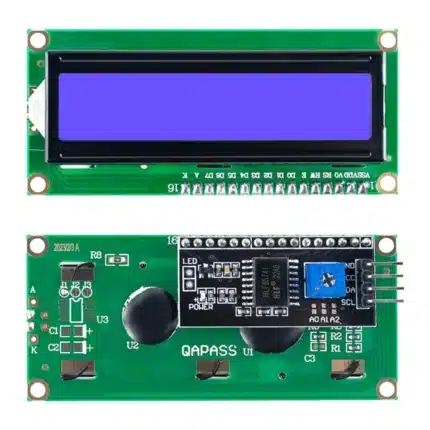
16×2 LCD Display with I2C Interface – Blue Backlight
Display your project data with only four connections. This 16×2 LCD comes with the I2C backpack already soldered, making it ready to use without additional soldering.
Display: 16 characters × 2 lines
Backlight: Blue with white characters
Interface: I2C (VCC, GND, SDA, SCL)
Operating Voltage: 5V DC
Contrast: Adjustable onboard potentiometer
Beginner Friendly: I2C adapter already soldered
Best For: Arduino, ESP32, Raspberry Pi, IoT and STEM projects
A 16×2 character LCD provides two rows of 16 characters, while using an I2C interface greatly reduces the number of microcontroller connections required compared with the standard parallel interface.
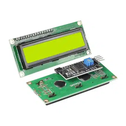
16×2 LCD Display with I2C Interface – Yellow Backlight
A clear, beginner-friendly 16×2 character display with the I2C backpack already soldered. The yellow-green backlight provides excellent readability while the I2C interface reduces wiring to only four connections.
Display: 16 characters × 2 lines
Backlight: Yellow-Green
Interface: I2C (VCC, GND, SDA, SCL)
Voltage: 5V DC
Contrast: Adjustable
Installation: Ready to use – no backpack soldering required
Best For: Arduino, ESP32, Raspberry Pi, IoT and educational projects
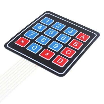
4×4 Matrix Membrane Keypad | 16 Button Keypad Module
The standard keypad for security projects. This ultra-thin 16-button keypad allows users to enter passwords, navigate menus, or control robots. It features a peel-and-stick adhesive backing, making it easy to mount on any plastic project box or door.
-
Keys: 16 (0-9, A-D, *, #)
-
Mounting: Self-Adhesive Backing (Peel & Stick)
-
Interface: 8 Pins (Standard 2.54mm header)
-
Best For: Electronic Door Locks, Calculators, and Attendance Systems.

DHT11 Temperature and Humidity Sensor Module | Digital Weather Station
The #1 sensor for weather projects. The DHT11 is the most affordable way to measure ambient temperature and humidity. It provides calibrated digital signal output, making it perfect for automatic fan controllers and weather stations.
-
Measures: Temperature (0-50°C) & Humidity (20-90%)
-
Interface: Single Wire Digital (Easy Arduino Connection)
-
Includes: 3-Pin Breakout Board + Jumper Wires (Check your stock to confirm wires!)
-
Ideal For: Smart homes, greenhouses, and environment monitoring.
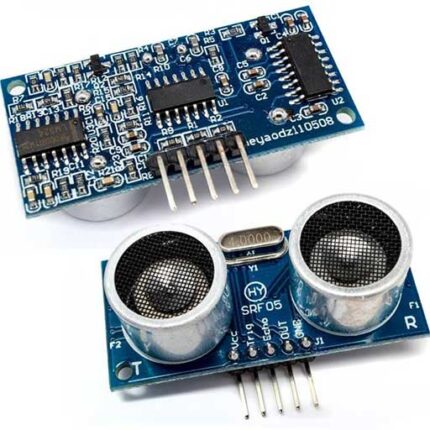
HC-SR04 Ultrasonic Sensor Module | Distance Measurement for Arduino
Give your robot eyes. The HC-SR04 uses sonar (sound waves) to measure distance, just like a bat. It is the standard sensor for obstacle avoidance robots and water level monitoring systems.
-
Range: 2cm to 400cm (4 Meters)
-
Accuracy: 3mm
-
Pins: VCC, Trig, Echo, GND
-
Best For: Obstacle avoiding cars, reverse parking sensors, and tank level detection.

IRF520 MOSFET Driver Module (0-24V) | PWM Motor & LED Controller
The easiest way to drive 12V/24V loads. This breakout board allows your Arduino to control high-voltage devices like LED strips, DC motors, and solenoid valves using the IRF520 MOSFET. It features screw terminals for easy wiring—no soldering required!
-
Max Load: 24V DC / < 5A.
-
Control Voltage: 3.3V or 5V (PWM Compatible).
-
Output: Pulse Width Modulation (Speed/Dimming control).
-
Best For: LED Strips, Small DC Fans, and Solenoids.

NEO-6M GPS Module V2 with Ceramic Antenna | Flight Controller & Tracker
Add Satellite Navigation to your project. This high-precision GPS module allows your Arduino, ESP32, or Drone to know its exact location, speed, and time. It comes with a detachable ceramic antenna and a built-in backup battery for fast "Hot Starts."
-
Chipset: U-Blox NEO-6M.
-
Antenna: High-gain Active Ceramic Antenna (Included).
-
Data Retention: EEPROM + Battery (Saves configuration).
-
Best For: Drone Flight Controllers, Vehicle Trackers, and Speedometers.

Raindrop Sensor Module | Rain & Water Detector for Arduino
Build your own weather station. This sensor detects rain, snow, or water droplets. It consists of a large nickel-plated sensing board and a control module. When water hits the board, it sends a signal to your Arduino to close windows or sound an alarm.
-
Sensor Type: Resistive (Nickel-Plated Board).
-
Outputs: Digital (High/Low) and Analog (Rain Intensity).
-
Durability: Treated against oxidation for longer life.
-
Best For: Automatic Wipers, Smart Clotheslines, and Weather Stations.
Reviews
There are no reviews yet.